
Sample project. This page illustrates how we document a project like this. Names, sizes and figures are illustrative, not a record of completed work.
1840 CONEY ISLAND AVENUE MIDWOOD,NY 11230
Service: MEP Design & Engineering
Midwood, Brooklyn, NYHealth + Wellness
- Mechanical
- Electrical
- Plumbing
- Fire Sprinkler & Standpipe
- Energy Compliance (COMcheck)
- Backflow Applications
- DOB Filing Sets
- Levels, from the cellar to the roof (about 50 ft)
- 5
- Dialysis stations, each with a treated-water and drain connection
- 24
- VRF heat pump capacity across 4 outdoor units
- 62tons
- Gas-fired rooftop units (2 × 15-ton)
- 30tons
- Sprinkler and hose demand, calculated against a city hydrant test
- 460gpm
- Drawing sheets in the mechanical, plumbing, sprinkler and energy sets
- 40
Project information
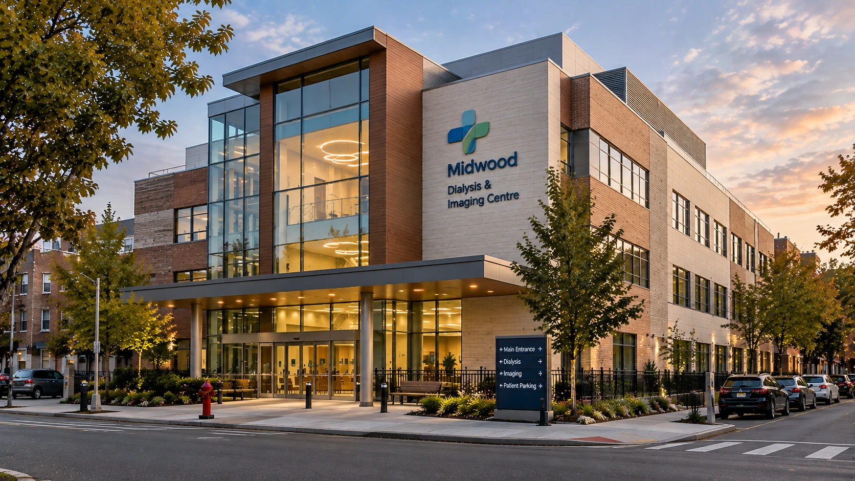
A new outpatient building on a Brooklyn avenue with a cellar for plant and storage, a ground-floor imaging and consultation suite, and two floors above. The second floor holds a 24-station dialysis unit, which needs ultra-pure water piped to every chair, stable temperatures and a reliable drain at each station. All of it had to be designed to the NYC Construction Codes and the 2020 NYC Energy Conservation Code. Like every New York project, the design also has to satisfy the NYC Construction Codes and the city's energy code requirements.
How We Helped 1840 CONEY ISLAND AVENUE MIDWOOD,NY 11230
Mechanical: we scheduled ventilation room by room for about 26,600 ft² of rooms, with the highest outdoor-air rate on second floor (dialysis). Heating and cooling come from a VRF heat pump system of 4 outdoor units totalling about 62 tons and 58 indoor units, backed by 2 15-ton gas-fired rooftop units and 2 energy-recovery ventilators. A cellar treatment room feeds a continuously circulating treated-water loop to every station, with a floor-mounted drain box at each chair. Electrical: we scheduled the power connection for every rooftop unit, VRF unit, fan, heater and pump — voltage, phase, minimum circuit ampacity and overcurrent protection — and sized the building service for the connected load. Plumbing: A duplex variable-speed booster set supplies domestic water, two 100-gallon gas-fired heaters supply hot water with recirculation, and a duplex sump keeps the cellar drained. Fire protection: a wet sprinkler system on a 6-inch combined sprinkler and standpipe riser fed directly from the city main, hydraulically calculated at about 460 gpm against the city hydrant test. We also prepared the COMcheck energy analysis, the backflow prevention applications and the mechanical, plumbing and sprinkler sets for filing.
The brief
What the project needed, and how we answered
- 01
Deliver ultra-pure water and a clean drain to 24 dialysis stations.
A cellar treatment room feeds a continuously circulating treated-water loop to every station, with a floor-mounted drain box at each chair.
- 02
Heat and cool every room of the dialysis and imaging centre with its own comfort setting.
A VRF heat pump system of 4 outdoor units (12, 16, 16, 18 tons) serves 58 indoor units, so every exam room, treatment bay and office is controlled on its own.
- 03
Bring in enough fresh air for a building with little roof space.
2 15-ton gas-fired rooftop units with reheat and economizers, plus 2 energy-recovery ventilators, deliver about 5,400 cfm of outdoor air across the scheduled rooms.
- 04
Get water in and waste out reliably.
A duplex variable-speed booster set supplies domestic water, two 100-gallon gas-fired heaters supply hot water with recirculation, and a duplex sump keeps the cellar drained.
- 05
Power every unit, pump and heater safely, with a service sized for the load.
Each piece of equipment was scheduled with its voltage, phase and circuit ampacity, from 2 rooftop units and 4 VRF outdoor units at 460 V, 3-phase down to 120 V unit heaters, and the building service was sized to the total.
- 06
Protect the building in a fire.
A wet sprinkler system on a 6-inch combined sprinkler and standpipe riser and street connections for the fire department.
- 07
Clear the approvals that gate construction.
We prepared the COMcheck energy analysis, the backflow prevention applications, the hydraulic calculations and the mechanical, plumbing and sprinkler sets for filing.
System by system
What we designed, with the numbers
An air-cooled VRF system: 4 outdoor heat pump units feed 58 ducted and ceiling-type indoor units, each with its own thermostat and condensate pump.
- Outdoor units
- 4 units: 12, 16, 16, 18 tons — 62 tons nominal
- Cooling capacity
- About 744,000 Btu/h in all
- Indoor units
- 58 units, 0.5 to 3 tons
- Refrigerant
- R-410A, with long-line sets where piping exceeds standard lengths
- Electrical
- 460 V, 3-phase outdoor units; 208–230 V, 1-phase indoor units
- Controls
- Low-ambient operation, compressor cycle protection, MERV 8 filters on returns
Building cross-section
Inside the building, level by level
Select a level to see what we designed on it. Elevations are the project datum shown on the riser diagrams; street 98.50.
Drawn to scale from the floor-to-floor heights · numbers are elevations in feet
EL 112.00 ft
Second floor
The dialysis unit: 24 stations, a nurse station and the treated-water loop.
- Rooms scheduled
- 7,100 ft²
- Dialysis stations
- 24
- Outdoor air
- 1,900 cfm
Mechanical
Higher outdoor-air rate and individual comfort control across the dialysis floor, with the largest rooftop unit assigned here.
Plumbing
Treated-water loop with a connection and floor-mounted drain box at every station, and a hot-water recirculation line.
Fire protection
Sprinklers and standpipe hose valves fed from the combined riser.
Electrical
Single-phase connections for each VRF indoor unit, plus electric unit heaters and restroom heaters on this level.
Deliverables
What we issued
The filing sets and the calculations behind them.
18sheets
Mechanical
Plans for every level, air-flow and refrigerant risers, details and equipment schedules
12sheets
Plumbing
Plans, sanitary, gas and storm risers, details and schedules
6sheets
Sprinkler & standpipe
Plans for all levels, specifications, details and the riser diagram
4sheets
Energy analysis
COMcheck mechanical and plumbing compliance, certificates and inspection checklists
14pages
Hydraulic calculations
Node and pipe data, supply curve and demand for the sprinkler design
3sheets
Backflow applications
Fire and domestic service plans and application forms
Engineering data
Where the building's air goes
We scheduled outdoor air and exhaust for every room. The bars show how those flows are shared between the levels, and why second floor (dialysis) leads.
Outdoor air supplied
5,400 cfm in total
Design flow to rooms, by level
- Second floor (dialysis)35%
- First floor27%
- Third floor23%
- Cellar15%
Share of 5,400 cfm
Air exhausted
2,240 cfm in total
Design flow from rooms, by level
- Second floor (dialysis)29%
- First floor23%
- Third floor21%
- Cellar27%
Share of 2,240 cfm
- Rooms scheduled
- 26,600 ft²
- Outdoor air
- 5,400 cfm
- Exhaust
- 2,240 cfm
- Indoor units
- 58
Second floor (dialysis) takes 35% of the building's outdoor air, which is why it has the most careful air-flow design.
Fire water
How the city supply covers the sprinklers
We calculated the sprinkler system against a flow test on the city main. At the flow the sprinklers and hose stream demand, the street still delivers more pressure than the system needs, so no fire pump is required.
- Test
- Hydrant flow test on the city main
- Static pressure
- 62 psi
- Residual
- 56 psi at 600 gpm
- System demand
- 460 gpm at 49 psi
- Hazard
- Light, wet system
- Hose allowance
- 100 gpm
The flow-test curve stays about 9 psi above the system's demand at 460 gpm, so the city supply is enough on its own.
Why EDGE
15+ years of MEP engineering experience
Every discipline, every building type
HVAC, electrical, plumbing and fire protection for new buildings, renovations, fit-outs and franchise programs — one team, one set of coordinated drawings.
Quality checked by engineers
Every drawing set, model and calculation is reviewed by an experienced engineer before it reaches you.
One partner from design to shop drawings
MEP design, energy compliance and shop drawings from one team — fewer handoffs and a single point of contact.
Next step
Have a similar project?
Send one drawing set and see our work on your own project before you decide.
- Free, no commitment
- NDA before any files
- An engineer replies within one business day