
209 Barlow Drive South
Service: MEP Design & Engineering
Mill Basin, Brooklyn, NYResidential
- Mechanical
- Electrical
- Energy Compliance (REScheck)
- DOB Filing Set
- VRF heat pump serving the whole house
- 5ton
- Indoor units, each with its own controller
- 4
- Hydronic radiant floor zones
- 6
- Conditioned floor area modelled
- 2,158ft²
- New single-phase electrical service
- 200A
- Sheets in the DOB filing set
- 25
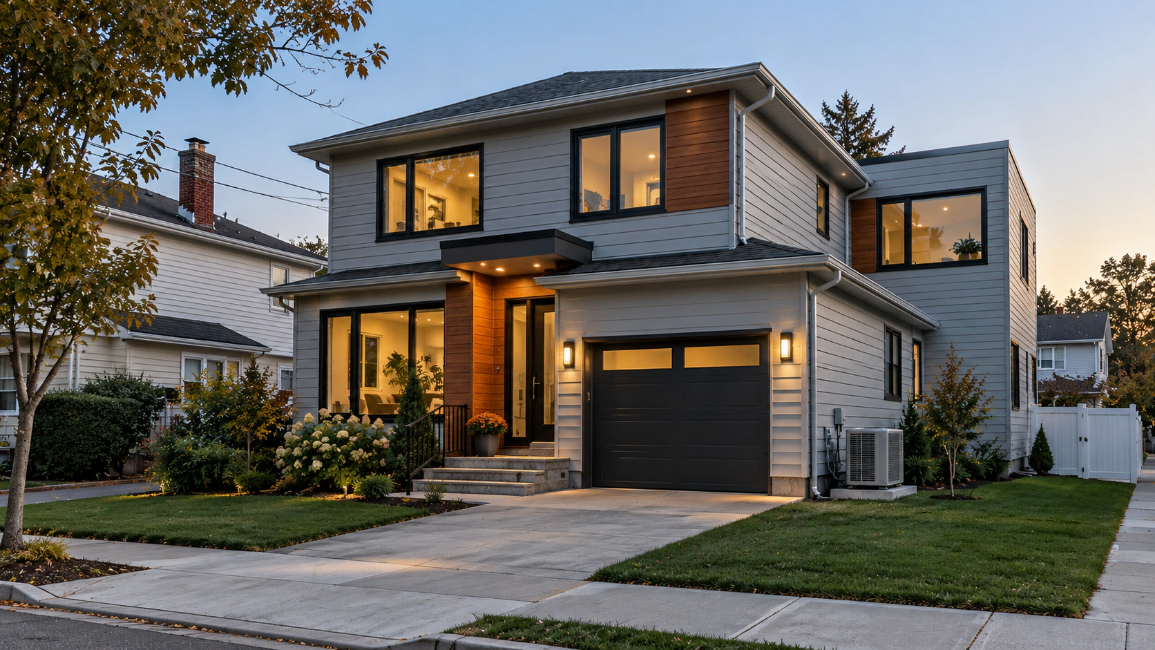
Project information
The house is a two-storey wood-frame residence with an attached garage. The renovation removes the existing interior partitions, bathrooms and kitchen, adds a rear extension with a new master bedroom, walk-in closet and master bath, and relocates the boiler room. The owner wanted quiet, even comfort on both floors without bulky ductwork in the living spaces, with warm floors throughout. Like every New York project, the design also has to satisfy the NYC Construction Codes and the city's energy code requirements.
How We Helped 209 Barlow Drive South
We ran room-by-room heating and cooling loads and zoned the house by floor, then designed a split approach: a single 5-ton VRF heat pump serving four indoor units — two wall-mounted units on the first floor and two concealed ducted units upstairs — at a 110% connection ratio, with refrigerant piping and condensate routing coordinated room by room. Heating comes primarily from hydronic radiant floors (panels on a glycol loop with floor and wall temperature sensors per zone), fed by a new high-efficiency combi boiler in the relocated boiler room. We added bathroom (50 CFM) and kitchen (150 CFM) exhaust, sized the 200 A, 120/208 V single-phase service and panel, laid out lighting and power for both floors, prepared the REScheck energy compliance and issued the mechanical and electrical drawing sets for NYC DOB filing, including revisions through plan review.
The brief
What the project needed, and how we answered
- 01
Cool both floors without bulky ductwork in the living spaces.
Slim wall-mounted VRF units on the first floor and two concealed ducted units for the second floor, all on one outdoor heat pump. Small refrigerant lines (¼" to ¾") run to each unit instead of large supply ducts.
- 02
Warm floors throughout, over both hardwood and tile.
Hydronic radiant panels on a glycol loop, split into six zones. Each zone has a floor and a wall temperature sensor, and every circuit has its own 2-way zone valve, so each room holds its setpoint without overheating the floor finish.
- 03
Move the boiler room as part of the renovation.
A new high-efficiency combi boiler in the relocated room, piped through a low-loss header with a mixing valve, expansion tank and condensate neutralizer, and with sealed-combustion intake and exhaust piped to outside.
- 04
The outdoor unit sits 10 ft below the indoor units.
We checked the refrigerant layout against the manufacturer's limits: the longest run is 38 ft against a 394 ft limit, and the height difference is well inside the 131 ft allowed. Three refnet joints split the lines to the four units.
- 05
Get the work through NYC Department of Buildings review.
Mechanical, electrical and energy-code sheets were coordinated and issued together as one filing set, including fire-rated penetration details and a REScheck energy analysis.
System by system
What we designed, with the numbers
One 5-ton VRF heat pump serves four indoor units at a 110% connection ratio. It covers the full cooling load and adds heating capacity alongside the radiant floors.
- Outdoor unit
- VRF heat pump, 5 ton, R-410A
- Cooling capacity
- 61,000 Btu/h at 95°F outdoors
- Heating capacity
- 48,300 Btu/h at 12°F outdoors
- Connection ratio
- 110% (66,000 Btu/h of indoor units)
- Indoor units
- 2 wall-mounted (first floor), 2 concealed ducted (second floor)
- Controls
- One wired navigation remote per indoor unit
- Refrigerant piping
- ≈152 ft of ¼"–¾" line, 3 refnet joints, longest run 38 ft
- Refrigerant charge
- 9.8 lb total (7.9 lb factory + 1.8 lb added)
- Condensate
- Float switches and condensate pumps on the ducted units
Engineering data
Where this house gains and loses heat
We ran room-by-room heating and cooling load calculations before choosing any equipment. The breakdown shows where the house gains heat in summer and loses it in winter.
Summer cooling
3.5 tons at the coil
Peak at 4 pm in July · 92°F dry bulb / 74°F wet bulb
- Walls21%
- Glass (sun)17%
- People14%
- Skylights (sun)12%
- Equipment10%
- Roof9%
- Ventilation air8%
- Glass conduction7%
- Infiltration2%
Share of 35,960 Btu/h
Winter heating
49,100 Btu/h design loss
Main house at design winter conditions
- Walls25%
- Floor20%
- Glass & doors17%
- Infiltration14%
- Ventilation air13%
- Roof6%
- Skylights4%
Share of 49,098 Btu/h
- Cooling intensity
- 19.2 Btu/h·ft²
- Floor area per ton
- 626 ft²/ton
- Heating intensity
- 27.7 Btu/h·ft²
- Supply airflow
- 0.80 cfm/ft²
Walls, glass and skylights make up more than half of the summer peak. In winter, the walls and the floor lead the heat loss.
Why EDGE
15+ years of MEP engineering experience
Every discipline, every building type
HVAC, electrical, plumbing and fire protection for new buildings, renovations, fit-outs and franchise programs — one team, one set of coordinated drawings.
Quality checked by engineers
Every drawing set, model and calculation is reviewed by an experienced engineer before it reaches you.
One partner from design to shop drawings
MEP design, energy compliance and shop drawings from one team — fewer handoffs and a single point of contact.
Next step
Have a similar project?
Send one drawing set and see our work on your own project before you decide.
- Free, no commitment
- NDA before any files
- An engineer replies within one business day