
Essem Industries, Bhamboli
Service: MEP Design & Engineering
Bhamboli, Pune, MaharashtraIndustrial / Manufacturing
- External Plumbing & Water Supply
- Rainwater Harvesting & Aquifer Recharge
- Storm & Sewage Drainage
- Fire Pump Room Piping
- Utility Coordination
- Plot served by the external layout
- 15,998m²
- Annual rainwater potential of the developed site (design)
- 10,607m³
- Recharge bores, 160 mm wide and 60 m deep
- 8
- Rainwater capacity provided, above the requirement
- 498m³
- Resistivity soundings, 70 to 90 m deep, behind the design
- 5
- Issues of the external plumbing layout, to May 2026
- 11
Project information
An industrial plant on a plot of about 15,998 m² at Bhamboli, in Pune district, with process areas for pickling, passivation and anodizing, a demineralised-water plant, its own effluent treatment plant (anoxic, aeration and membrane stages, ultrafiltration, reverse osmosis, an evaporator and a sludge drying bed), a generator, the electricity board's transformer room, a pump room above underground tanks and a toilet block, behind a compound wall on a proposed 15 m road. The process equipment and the plant's civil layout are the client's; our work is the water that goes in, the water that leaves, and the rain that falls on it. Three things make that unusual. The ground is Deccan basalt, a layered rock where groundwater is patchy and unpredictable. A plant of this kind uses large volumes of water and sends effluent to a treatment plant that must never be fed by stormwater. And the development covers almost the whole plot with roofs, roads and paving, with only about 475 m² left as soft ground, which raises the site's runoff by about 171 m³ on a design rainy day.
Gallery
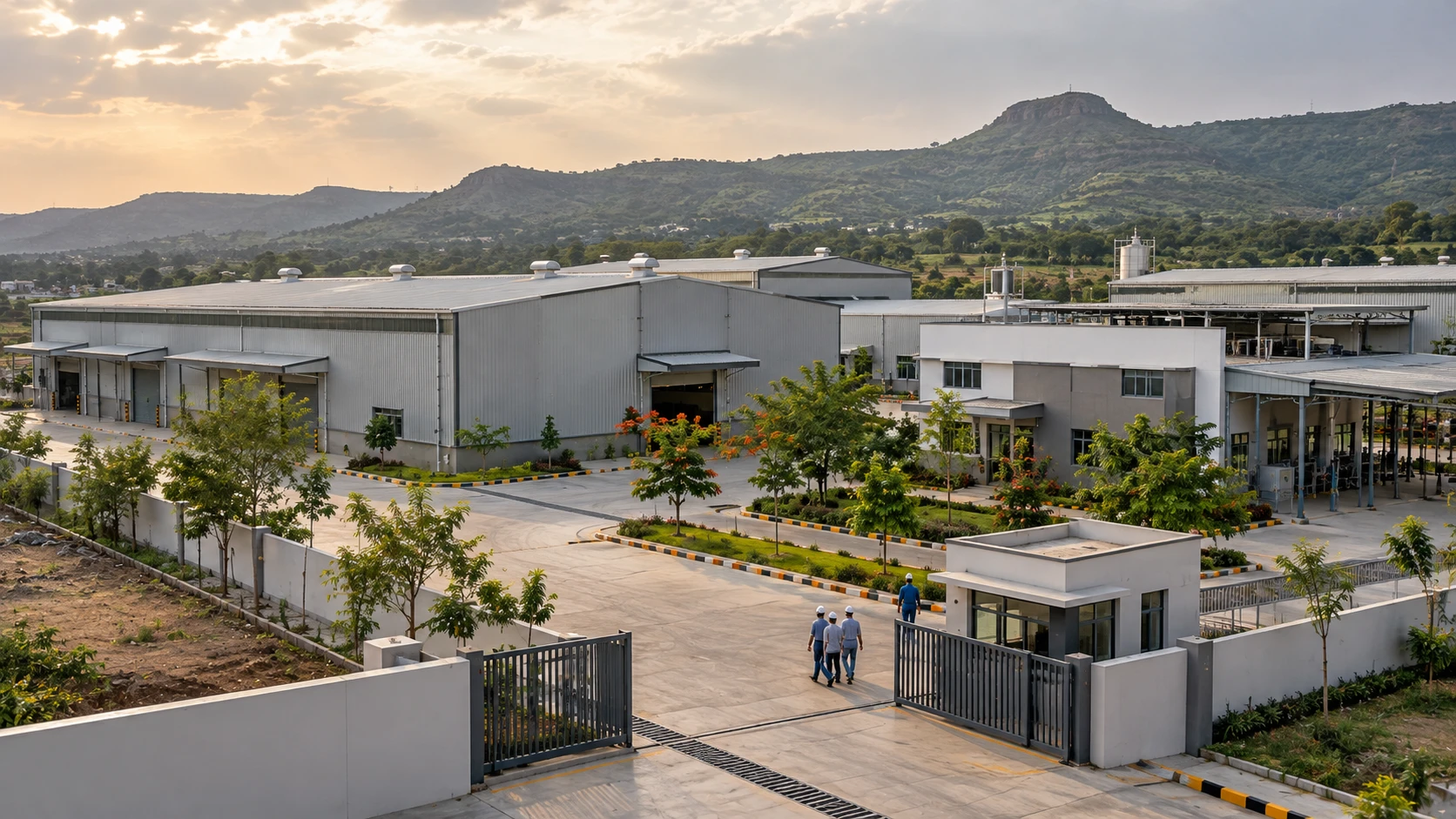
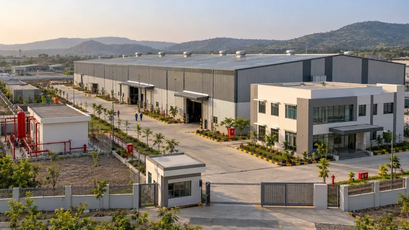
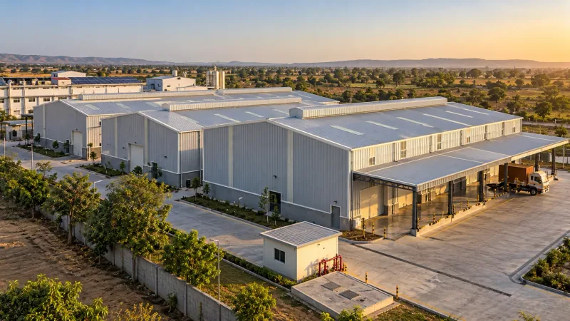
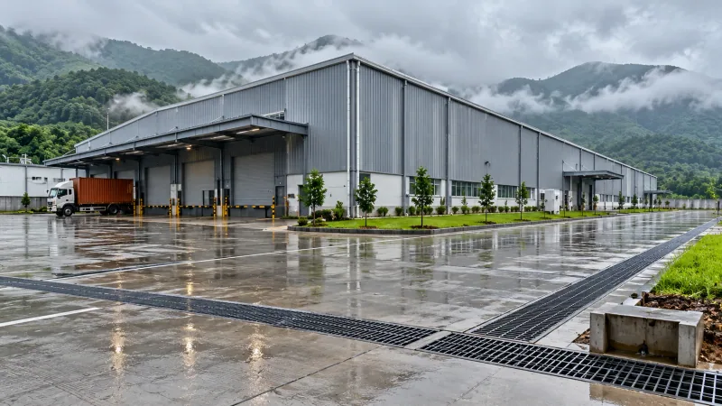
Essem Industries, Bhamboli in renders
Illustrative renders of the building and its setting, not photographs of the finished site. Select an image to enlarge it.
How We Helped Essem Industries, Bhamboli
We designed the external plumbing layout, now at its eleventh issue, and worked from an independent hydrogeological assessment of the site rather than assuming the ground would take water. The assessment, based on resistivity soundings at five points to depths of 70 to 90 m and a percolation test, classed the strata, found the weathered and fractured basalt zone and recommended recharge from low to moderate rates through bores. We carried that into the drawings as rainwater harvesting: roof and road runoff collected through 160 mm terrace downtakes that discharge at ground level, 150 mm gutters, 300 and 450 mm trenches under perforated gratings, 450 x 450 mm chambers and RCC storm pipes, then led to de-silting pits and main recharge pits with a filter and a bore, so that silt and oil are removed before water reaches the aquifer. The hydrogeologist's water budget (about 10,607 m³ of rain a year after development, against 6,882 m³ before) calls for a 300 m³ rooftop tank and eight recharge bores of 160 mm diameter and 60 m depth, which together give about 498 m³, more than the requirement. Water supply: bore-well and tanker inlets into 20,000-litre raw water tanks, softeners above the underground tank (with a 4 m clear height reserved), a 20,000-litre treated water tank, a 40,000-litre domestic tank, and 10,000-litre domestic and 5,000-litre flushing tanks for the toilet block of 15 closets, with a rising main for filling the overhead tank, a domestic riser and a flushing riser. Drainage: 450 x 900 mm sewage chambers and 150 mm RCC sewage pipes at depths worked out chamber by chamber (invert levels from 104.8 down to 103.3 m on a 1 in 300 slope), the plant's overflow pumping line, and a 450 mm road-crossing provision with its chamber. Fire water: the pump room piping with a 200 mm suction header, 150 mm common and sprinkler delivery headers, five numbered pump sets, non-return, gate and butterfly valves, strainers, rubber bellows, air vessel, pressure gauges and a test line, and the downcomer for the internal hydrants. Coordination: the gas line saddled to the compound wall and crossed through a 300 mm hume pipe, electrical chambers left to the electrical consultant, and the changes of 2026 - an added rain water chamber, a revision after a site meeting, and the final one at the client's request in May 2026.
The brief
What the project needed, and how we answered
- 01
Water for a process plant that does not depend on one source.
Bore-well and tanker inlets feeding 20,000-litre raw water tanks, softeners above the underground tank, a 20,000-litre treated water tank and a 40,000-litre domestic tank, with a rising main to the overhead tank and separate domestic and flushing risers.
- 02
Put the rain back into the ground, in rock that does not like to take it.
A recharge scheme sized from the hydrogeological study of the Deccan basalt: runoff led through gutters, trenches and chambers to de-silting pits and recharge pits with a filter and a 60 m bore, with a 300 m³ rooftop tank, giving about 498 m³ of capacity.
- 03
Move the water off a flat site.
Roof downtakes that discharge at ground level, trenches of 300 and 450 mm under perforated gratings, 450 x 450 mm chambers and RCC NP-3 pipe laid to a surface slope of 1 in 300, with every invert level and depth written on the plan.
- 04
Keep effluent and stormwater apart.
Separate sewage chambers and 150 mm sewage pipes, the effluent plant's overflow pumping line carried on a saddle at the compound wall, and a separate flushing supply, so nothing from the plant is meant to reach the rain system or the recharge bores.
- 05
Fire water that is ready at any hour.
A pump room with a 200 mm suction header, 150 mm delivery headers for the hydrants and the sprinklers, five numbered pump sets, valves, strainers, bellows, an air vessel, gauges and a test line.
System by system
What we designed, with the numbers
Bore well, tanker and treated water feed raw, treated, domestic and flushing tanks, with softeners placed above the underground tank.
- Sources
- Bore-well water supply inlet and tanker water supply inlet
- Raw and treated water
- 20,000-litre raw water tanks and a 20,000-litre treated water tank, each 2.1 m deep with a 0.3 m free board
- Softeners
- Above the underground tank, on a 3.0 x 4.0 m footprint with 4.0 m clear height reserved
- Domestic water
- 40,000-litre domestic tank; a rising main to fill the overhead tank; domestic riser
- Toilet block
- 10,000-litre domestic and 5,000-litre flushing tanks for 15 closets; flushing riser and downtake
- Connections
- 65 mm inlet and 40 mm outlet at the tanks; water tapping for the kitchen and toilets
Why EDGE
15+ years of MEP engineering experience
Every discipline, every building type
HVAC, electrical, plumbing and fire protection for new buildings, renovations, fit-outs and franchise programs — one team, one set of coordinated drawings.
Quality checked by engineers
Every drawing set, model and calculation is reviewed by an experienced engineer before it reaches you.
One partner from design to shop drawings
MEP design, energy compliance and shop drawings from one team — fewer handoffs and a single point of contact.
Next step
Have a similar project?
Send one drawing set and see our work on your own project before you decide.
- Free, no commitment
- NDA before any files
- An engineer replies within one business day