
Forging Plant, Shirdi MIDC
Service: MEP Design & Engineering
Shirdi, MaharashtraIndustrial / Manufacturing
- Environmental Clearance
- Load Demand & Transformer Sizing
- 33 kV Single-Line Diagram
- DG Sets
- Energy Conservation
- Solar PV
- EV Charging
- Street Lighting
- Water Demand
- STP
- External Plumbing & Fire Layouts
- Connected load of the two plants, with 17,470 kW of demand at 0.8
- 21,837kW
- Installed on a 33 kV supply (2 x 2,250 and 4 x 5,000 kVA), against 20,552 kVA of maximum demand
- 24,500kVA
- Rooftop solar: 3,882 panels of 540 W, about 3.14 million kWh a year
- 2,096kW
- Of annual energy saved by solar, solar street lights and efficient drives
- 8.07%
- EV charging points in four stations, for 30% of the car bays
- 180
- Fire-water storage in two tanks, with 45 kL domestic and 15 kL flushing storage
- 450kL
Project information
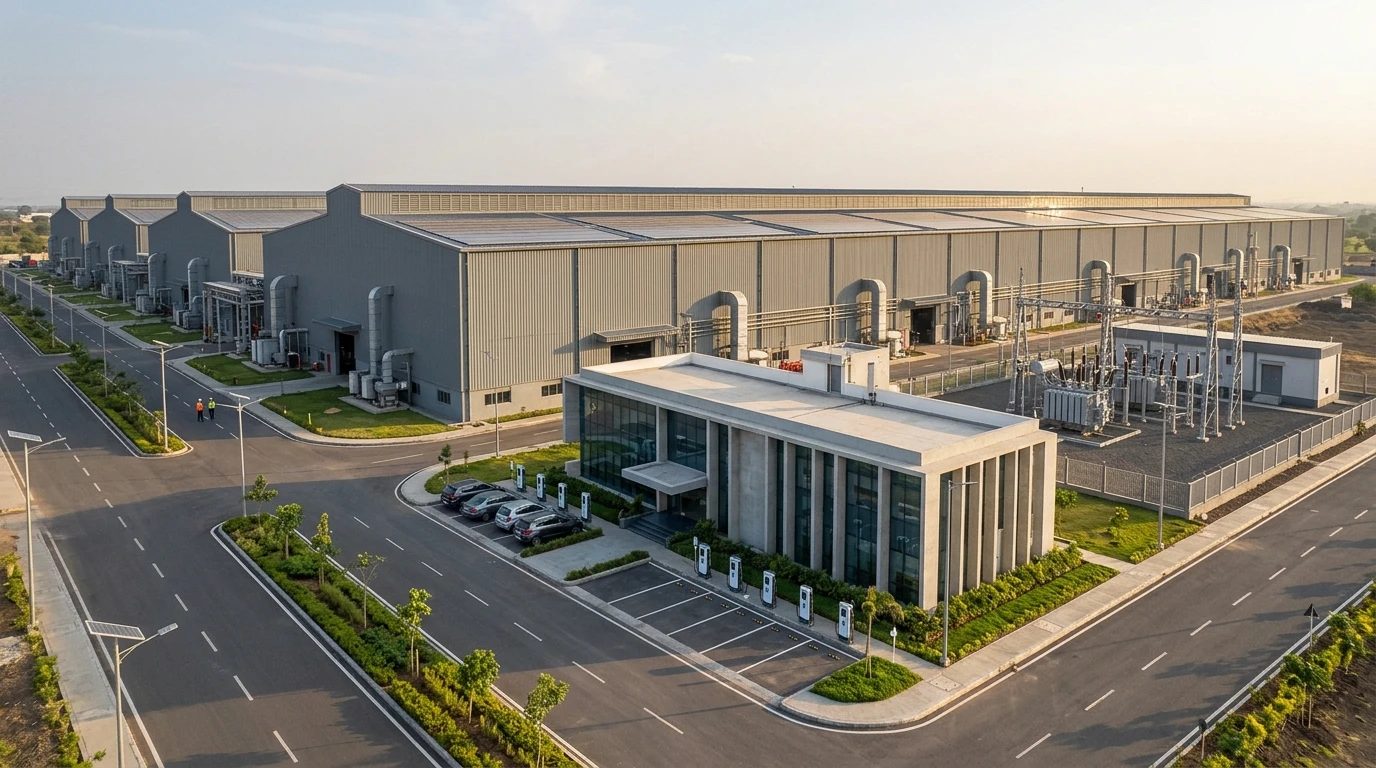
A forging plant on a plot of about 40 hectares in the industrial area at Shirdi, with 1,44,414 sq m of construction: one 17.5 m high production shed of 536.8 x 74.66 m (about 40,075 sq m), five 15 m high sheds of 256.56 x 72 m (18,475 sq m each) and a two-storey administration building, with material storage, lean-to sheds for utilities and open space for transformers, tanks and treatment plants. The process is power-hungry - induction heaters, forging and nosing presses of 1,200 to 2,200 kW, heat-treatment furnaces, CNC machining and hot and cold water systems - so the first questions were how much power the plant needs, how it is brought in and where it sits on the plot. The environmental clearance also asks how the plant saves energy, charges vehicles and treats and reuses water, and every answer has to be drawn on the plot.
Gallery
Forging Plant, Shirdi MIDC in renders
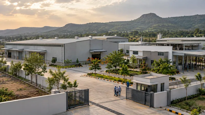
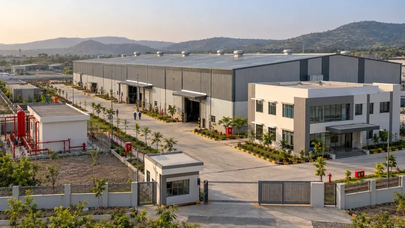
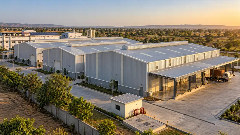
Illustrative renders of the building and its setting, not photographs of the finished site. Select an image to enlarge it.
How We Helped Forging Plant, Shirdi MIDC
Power: we listed every machine of the two plants line by line - 21,837 kW connected and 17,470 kW of demand at 0.8 - and sized the supply from it: 20,552 kVA at 0.8 maximum demand, met by two 2,250 kVA (33 kV / 575 V) and four 5,000 kVA (33 kV / 433 V) transformers, with a 33 kV SF6 switchboard of vacuum breakers, an 8,000 A busbar on the 433 V side and 7%-reactor power-factor panels of 1,500 kVAr. Two 500 kVA diesel sets carry the essential load of about 856 kW: sheds, offices, street lights, fire-water, effluent and sewage treatment. Energy: the clearance calls for savings, so we sized rooftop solar at 12% of demand - 2,096 kW from 3,882 panels of 540 W, about 3.14 million kWh a year - solar street lights on 591 fittings, and variable-frequency drives on conveyors, cranes, fans and pumps, which together save 4.12 million kWh a year, 8.07% of the plant's annual consumption. Charging: 30% of the car bays are given charging points - 180 in four charging stations. Water and drainage: a demand statement for 1,000 people and the landscape, domestic, flushing and fire storage (45 kL, 15 kL and 450 kL, in two fire tanks of 2.25 lakh litres with a 70 sq m pump room), a 45 to 50 kLD sewage plant, rainwater recharge pits with bore and filter, de-siltation pits and storm-water gutters, and a 150 mm fire-hydrant ring. We issued the sets in January and February 2026 and revised them as the architect's drawings changed.
The brief
What the project needed, and how we answered
- 01
Work out how much power a forging plant really needs.
Every machine of both plants was listed - induction heaters of 1,800 and 600 kW, forging and nosing presses of 2,200 and 1,200 kW, furnaces of 1,300 and 1,100 kW, CNC machines, pumps and compressors - 21,837 kW connected, 17,470 kW at 0.8 diversity, and 20,552 kVA at 0.8 maximum demand.
- 02
Bring it in at the right voltage and keep the plant on when the grid fails.
A 33 kV supply feeds a vacuum-breaker switchboard, two 2,250 kVA transformers at 575 V for the heating and press lines and four 5,000 kVA at 433 V on an 8,000 A busbar, with 1,500 kVAr power-factor panels; two 500 kVA diesel sets carry about 856 kW of essential services.
- 03
Show how the plant saves energy.
Rooftop solar of 2,096 kW (12% of demand), solar street lights on 591 fittings and variable-frequency drives on conveyors, cranes, fans and pumps save 4.12 million kWh of 51 million a year - 8.07%.
- 04
Charge the vehicles of a large workforce.
Charging points for 30% of the car bays - 180 points in four charging stations - drawn on the parking layout, with their load added to the demand.
- 05
Water, sewage and fire on a site of 40 hectares.
Demand for 1,000 people and the landscape, a 450 kL fire reserve in two tanks and a 70 sq m pump room, a 50 kLD sewage plant, rainwater recharge pits and a 150 mm hydrant ring, all drawn on the same plot plan as the electrical equipment.
System by system
What we designed, with the numbers
Six production sheds, an administration block, utilities and open space.
- Location
- Shirdi MIDC, Maharashtra
- Plot
- 3,99,408 sq m
- Construction
- 1,44,414 sq m
- Shed 01
- 536.8 x 74.66 m, 17.5 m high, about 40,075 sq m
- Sheds 02 to 06
- 256.56 x 72 m, 15 m high, 18,475 sq m each
- Administration
- Two ground-plus-one blocks of 70 x 81 m, 10 m high
- Utilities
- Lean-to sheds for transformers, DG sets, tanks, ETP, STP and DM / RO plant
Deliverables
The calculations and drawings behind the design
Issued for the environmental clearance in January and February 2026.
6pages
Energy conservation
Load schedule of both plants, transformer and DG sizing, solar, solar street lights, drives and the saving of 8.07% (R0 19 January, R1 4 February 2026).
5pages
Water demand
Demand, underground and overhead storage, sewage plant and reuse, with the dry- and wet-season balance (19 January 2026).
6sheets
External plumbing
Water supply, sewage, storm water, rainwater recharge and fire-hydrant layouts for the plot (R1, 2 February 2026).
4plans
Layouts
External MEP services, solar PV, EV charging and street lighting on the master plan (January and February 2026).
Engineering data
Where the power goes
Every machine of the two plants, grouped by what it does.
Connected load
21,837 kW
Both plants running, before diversity
- Forging & nosing presses6,80031%
- Induction heating4,96023%
- Heat-treatment furnaces2,40011%
- Finishing & process (hot water, paint, phosphating)1,9609%
- CNC machining & handling1,8428%
- Compressors & cooling-water pumps1,6408%
- Bands, pressing, testing & growing1,4507%
- Utilities, lighting & cranes7854%
Share of 21,837 kW
- Demand at 0.8
- 17,470 kW
- Maximum demand
- 20,552 kVA
- Transformers
- 24,500 kVA installed
- DG sets
- 2 x 500 kVA
Two machine types - presses and induction heaters - are more than half the plant's load, so the transformers, the 33 kV switchboard and the power-factor panels were sized around them.
Why EDGE
15+ years of MEP engineering experience
Every discipline, every building type
HVAC, electrical, plumbing and fire protection for new buildings, renovations, fit-outs and franchise programs — one team, one set of coordinated drawings.
Quality checked by engineers
Every drawing set, model and calculation is reviewed by an experienced engineer before it reaches you.
One partner from design to shop drawings
MEP design, energy compliance and shop drawings from one team — fewer handoffs and a single point of contact.
Next step
Have a similar project?
Send one drawing set and see our work on your own project before you decide.
- Free, no commitment
- NDA before any files
- An engineer replies within one business day